Download attachment: header.jpg Download attachment: image2.jpg Download attachment: image4.jpg Download attachment: next.jpg Download attachment: ScreenShot119.jpg
This is not complete, more of a work in progress for a project I'm working on right now.
Some thank you's first.
Ignacio Castano and Dennis Kovacs for helping out with some of the concepts from the paper for Gregory Patches last year. It would have taken me a lot longer to get this stuff together without them.
Rafael Grassetti for letting me play with his mechaGirl model ( http://grassettiart.com/ ).
What you are looking at:
- Full implementation of the paper: http://research.micr...cloop/sga09.pdf
- Graph based evaluation of gpu operations for skeletal -> morph -> dynamics -> tessellation.
- Graph based hlsl shader variation system. I don't write complete shaders. Shaders are built from the Render Pass + Mesh + Material + Light Setup + Environment state. A key is created for each unique request and search for in a database, if the request doesn't exist, the shader is evaluated, compiled and added to the database.
- SS,SSS from gpu pro... Still working on this, but the results of 1.5 hrs of work look good so far.
- I got so very sick of transparency screw ups, so I implemented the OIT linked list algorithm from AMD.
- Linear lighting pipeline
- Variance shadows.
Quick update:
[media]http://vimeo.com/34442499[/media]
- Old version of glow system, I really need to get an anamorphic blur in there.
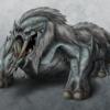
There are a number of R-G-B toned images in this post. Blue is regular patch, green is irregular patch, red is triangular patch).
How to do the same sort of thing for tessellation:
- I started with the nvidia meshtools, so download nvidia mesh tools from google code. Everything you need is in there providing you have a good idea of what you are doing.
- Download the nvidia sdk11 toolkit, this contains the quad (regular/irregular) pathways for gregory patches. You will have to modify quite a bit for a generalized pipeline, but it's an awesome start.
- Derive the triangular cases from the cpu tessellation code in the nvidia mesh tools.
- Plan your topology structures early. I went with a base topology class that could convert in different directions for tri, quad, quad dominant, patch etc... One day I'd like to write more about this... In essence, make sure that you can generalize your index / topology information early on.
- Write an exporter from your preferred DCC package (maya, 3dsmax, blender etc...)
- Ensure to use precise keyword in your GLSL / HLSL, Ignacio mentions this ( http://www.ludicon.c...ecise/#more-275 ) in one of his blog postings. Otherwise you will get cracks in your resulting mesh.
Questions / Comments / Criticism are welcome.
Revised... I like Pn actually.
Click here to view the iotd
🎉 Celebrating 25 Years of GameDev.net! 🎉
Not many can claim 25 years on the Internet! Join us in celebrating this milestone. Learn more about our history, and thank you for being a part of our community!
Gregory Patches and Character Stuff

"Graph based hlsl shader variation system. I don't write complete shaders. Shaders are built from the Render Pass + Mesh + Material + Light Setup + Environment state. A key is created for each unique request and search for in a database, if the request doesn't exist, the shader is evaluated, compiled and added to the database."
This sounds quite similar to something I've been working on for a little while, although I've had very little time recently to finish it. I called my system the Unified Rendering Virtual Machine. It is built on top of a graph of shader fragments which are stitched together and cached as a usable shader. Each part of the pipeline (eg. Mesh, Material, Light Setup, Environment state) adds its own fragments to the graph that will eventually be used to render a particular object.
The virtual machine part is where we mainly differ though, because I build my rendering pipeline out of commands that a very simple VM intemperates. The VM Commands include things like (although this is quite simplified): FetchVisibleObjects, AppendFragment, ApplyLighting, ApplyMaterials, CreateFullScreenQuad, FetchLightVolumes and OutputToRenderTarget. So these commands gather, create and act on an array of renderable objects, manipulating each object's shader graph.
With these commands you can build a forward renderer, deferred renderer, some hybrid, or anything you like. I named it the URVM because It unifies your post processing pipeline with your forward and deferred pipelines. Post-process effects are just commands going to the URVM.
I was wondering how you gather the shader constants that each stage of your pipeline (Render Pass + Mesh + Material + Light Setup + Environment state) and format them for submission with the cached/compiled shader? Since the shader that an object is using could change quite often as its environment or lighting changes, do you traverse the current shader graph of each object to acquire the constant data each time it is rendered? Or do you have some temporal cache for this data?

Author
With these commands you can build a forward renderer, deferred renderer, some hybrid, or anything you like. I named it the URVM because It unifies your post processing pipeline with your forward and deferred pipelines. Post-process effects are just commands going to the URVM.
That sounds similar to what I'm doing.And no, I don't have a command manager like you describe.
I was wondering how you gather the shader constants that each stage of your pipeline (Render Pass + Mesh + Material + Light Setup + Environment state) and format them for submission with the cached/compiled shader? Since the shader that an object is using could change quite often as its environment or lighting changes, do you traverse the current shader graph of each object to acquire the constant data each time it is rendered? Or do you have some temporal cache for this data?
At the moment I use DXSAS and poll a parameter value factory at shader load time for each parameters annotation. If the annotation does not name a type exposed by the database, a renderpass can be asked for the value provider.
For GLSL I'd have to wrap the shader up in xml to add meta information to the parameters as it has no semantic /annotation system.
A parameter value provider knows how to take the render arguments and get the value it needs and bind it to the shader. Shader parameter values also know how whether they are per render pass / per mesh etc... to control how often the value is updated by the calling shader.
I'm trying to implement the same approach (http://research.microsoft.com/en-us/um/people/cloop/sga09.pdf) for my master thesis.
Unfortunately I'm not quite clear regarding the formulas in chapter 3, I am hoping to get some answers maybe you can help!? You read this paper alot I'm sure ;)
I am unclear on the following points, did you figure them out?
- what kind of value do I get, when I calculate T(u,v,w) (a point?) and what do I do with the result?
- do I recieve the values u,v,w from the domain shader SV_DomainLocation or are they calculated?
- are the corner points in chapter 3.2 barycentric too?
- does v get replaced by p0 in figure 5?
- In chapter 3.3 Edge Points there is a formula for e0+, but none for e0-? For which edge is e0+ in figure 5? and how can I calculate e0+ for the other edges? It seems for me (figure 5) there are 5 edges, but just one e0+ is calculated, shouldn't there be 5 e0+?
- Do you maybe have a diagram of the controlpoints in relation to the control mesh? I am having problems seeing the big picture...
- In chapter 3.4: face points, you mention different transversal vectors r, r0+ and r0- but there is only one formula for r0+. Are r = r0+ = r0-? If not, how do I calculate r and r0-?
I am hoping you could point me in the right direction, thank you in advance!
Author
I'm trying to implement the same approach (http://research.microsoft.com/en-us/um/people/cloop/sga09.pdf) for my master thesis.
Unfortunately I'm not quite clear regarding the formulas in chapter 3, I am hoping to get some answers maybe you can help!? You read this paper alot I'm sure ;)
I am unclear on the following points, did you figure them out?
- what kind of value do I get, when I calculate T(u,v,w) (a point?) and what do I do with the result?
- do I recieve the values u,v,w from the domain shader SV_DomainLocation or are they calculated?
- are the corner points in chapter 3.2 barycentric too?
- does v get replaced by p0 in figure 5?
- In chapter 3.3 Edge Points there is a formula for e0+, but none for e0-? For which edge is e0+ in figure 5? and how can I calculate e0+ for the other edges? It seems for me (figure 5) there are 5 edges, but just one e0+ is calculated, shouldn't there be 5 e0+?
- Do you maybe have a diagram of the controlpoints in relation to the control mesh? I am having problems seeing the big picture...
- In chapter 3.4: face points, you mention different transversal vectors r, r0+ and r0- but there is only one formula for r0+. Are r = r0+ = r0-? If not, how do I calculate r and r0-?
I am hoping you could point me in the right direction, thank you in advance!
Sorry for the lateness in reply. I have not really kept up on my gamedev account  . I also stopped posting image of the day updates when they moved to twitter.
I think all of your questions are answered if you take a look at the evaluation code in nvmeshtools:
https://code.google.com/p/nvidia-mesh-tools/
Please PM me if you have any questions.
I would also suggest looking at OpenSubDiv. I've actually swapped out my old implementation for osd.
[video]https://vimeo.com/81872845[/video]
This topic is closed to new replies.
Advertisement
Popular Topics


Advertisement