Mesh data structures: Finding neighbouring edges of a vertex

Started by
11 comments, last by JoeJ 4 months, 1 week ago

Hi,

I am working with a directed edge data structure which is like the half-edge but more memory efficient. I am trying to determine the neighbouring edges given a vertex id. This is almost like finding the degree of a vertex. I am finding myself in an issue where if I try to find neighbouring edges of a vertex id which is part of a boundary edge, it ends up in an infinite loop. For example, when passing vertex id 2, it goes through edges 2 -> 26 -> 1 -> 17 -> 1 -> 17 -> and keeps looping between 1 and 17.

My Current thought process is to traverse the structure using next(halfedge[edge]) until we hit a boundary edge. This traversal is counterclockwise, once we hit a boundary edge we know we have explored the left side. We now need to flip to explore the right side so I trigger to boolean so we now start exploring clockwise to get the edges on that side until we once again hit a boundary edge.

I am quite confused on how you could find neighbouring edges given a vertex id and would appreciate any insight. This is what I am currently doing.

std::vector<int> Mesh::NeighbourEdges(int vertex_id)
{
    std::vector<int> neighbours;

    long startingEdge = firstDirectedEdge[vertex_id]; // fde for current vertex
    long currentEdge = startingEdge;
    bool otherside = false;
    do
    {
        // 2 -> 26 -> 1 -> 17 -> 1 -> 17 -> 1
        neighbours.push_back(currentEdge);

        if(halfedge[currentEdge] == -1)
        {
            currentEdge = prev(startingEdge);
            otherside = true;
        } else
        {
            if(!otherside)
            {
                currentEdge = next(halfedge[currentEdge]);
            } else
            {
                currentEdge = prev(halfedge[currentEdge]);
            }
        }

    } while (currentEdge != startingEdge);
    
    return neighbours;
}
Advertisement

TBH I have done quite a bit of mesh processing (e.g. in a few SIGGRAPH papers) and I've never used any of these fancy mesh data structures. The main issue with those is that they all require the mesh to be manifold (i.e. each edge can have no more than 2 adjacent faces). In the real world, this is often not the case. Every geometry processing system I've built has needed to handle these problematic cases, and so I used alternative data structures that are much simpler yet contain the information needed to handle non-manifold geometry gracefully. Maybe this is the problem you are seeing, that your mesh is not manifold and so the traversal breaks?

The data structure I have used looks something like this:

  • Vertices: array of (position, edge neighbor ID list)
  • Edges: array of (2 vertex IDs, face neighbor ID list)
  • Faces: array of (3 vertex IDs). I always assume triangles, but I guess it could be extended to polygons.

The main issue with this representation is making it performant. A naive implementation would result in many small allocations because each vertex and edge need to store a small list. This performance problem can be avoided using an optimization similar to the “short string optimization”. With this method, the neighbor lists have a small local storage (9 for vertex edge neighbors, 3 for edge face neighbors). The lists only allocate memory when growing beyond that size. The local storage covers the vast majority of cases, and so the number of allocations in practice is small.

Some mesh operations using this representation can be tricky, because you must be sure to maintain consistency of all of the inter-references. I've implemented stuff like very fast edge collapse simplification using this data structure, shipped in production code.

I have such function too:

void GetVertexAdjacentEdges (std::vector<int> &edges, const int vertex) const 
		{
			assert(vertex!=-1);
			int eI = GetVertexEdge(vertex);
			if (eI==-1) return;
			do {
				edges.push_back(eI);
				eI = GetEdgePair(eI);
				eI = GetEdgeNext(eI);
			} while (eI != GetVertexEdge(vertex));
		}

It's bad for some reasons and i should remove it, but seems the same thing you try to do.

snoken said:
This traversal is counterclockwise, once we hit a boundary edge we know…

You assume that boundary cases affect a vertex traversal? If this would be true, it would be a very bad data structure, adding complexity for no reason. Nobody would use it.
So i stop here and assume your code follows the wrong idea.

Personally i imagine the vertex traversal like a star, walking around its tips. A tip is made from an half edge of the vertex and it's pair, which brings us the the next tip.
Contrary, the polygon traversal is simpler. We just follow the next pointer and don't need any pairs.

@JoeJ Thanks for the reply! I think the idea is the same with mine too. To get the degree of a vertex, it's fairly simple you just do next(halfedge[edge]) and you go around the star like you described. The issue im having with my current approach is that it begins to infinity loop. I think is due to the boundary edge check where I do:

 if(halfedge[currentEdge] == -1)
 {
 	currentEdge = prev(startingEdge);
 }

Im not sure how to handle this correctly because say we have just a single triangle, this will infinitely loop around that triangle, I think I need to add another condition to make it stop but I'm not sure what to use.

snoken said:
I think is due to the boundary edge check where I do:

Why do you think you would need such boundary check at all? You should not need it, and it should be irrelevant if you are on the boundary or not.

For an hypothetical answer, i could do this for example:
I could decide to not have half edges at the boundary. Then not all edges would have a pair, only those not at the boundary.
Technically it would work. But it would be a very idea. Because it makes the boundary a special case already for the data structure, even the simplest mesh processing would become a chore to implement.

Still, that case had happens for me, e.g. if i create a half edge mesh from indexed mesh. The boundary is missing after the initial construction.
So i added a post process to add it.

Maybe you are in a similar situation, and the data structures are not set up correctly. But what happens if you try a traversal like mine?

Aressera said:
The main issue with those is that they all require the mesh to be manifold (i.e. each edge can have no more than 2 adjacent faces). In the real world, this is often not the case.

Yeah. That's why i had asked about primary motivation in the other thread, but got no answer.

JoeJ said:
Yeah. That's why i had asked about primary motivation in the other thread, but got no answer.

Ok thanks, got it:

The goal is to do texture parameterisation

Posting here too because too many threads is confusing.

That's a good reason to use manifold data structures.

@JoeJ I'm following the details outlined here http://www.danenglesson.com/images/portfolio/MoA/halfedge.pdf​ for calculating per-vertex normals. They mention to get face normals and then calculate vertex normal by taking the normalized sum of the neighboring face normals. This is what I have done with the following code:


	// we now have face normals, begin calculating vertex normal
    for(int i = 0; i < vertices.size(); i++)
    {
            std::vector<int> neighbouringEdges = NeighbourEdges(i);
            vec3 sum = vec3(0.0f, 0.0f, 0.0f);
            for(int edge = 0; edge < neighbouringEdges.size(); edge++)
            {
                int face = neighbouringEdges[edge] / 3;
                sum = sum + normals[3 * face];
            }

            sum = sum / neighbouringEdges.size();
            sum.x = abs(sum.x);
            sum.y = abs(sum.y);
            sum.z = abs(sum.z);
            sum = sum.unit();
            vertexNormals.push_back(sum);
    }
    
    normals.clear();
    normals.insert(normals.begin(), vertexNormals.begin(), vertexNormals.end());

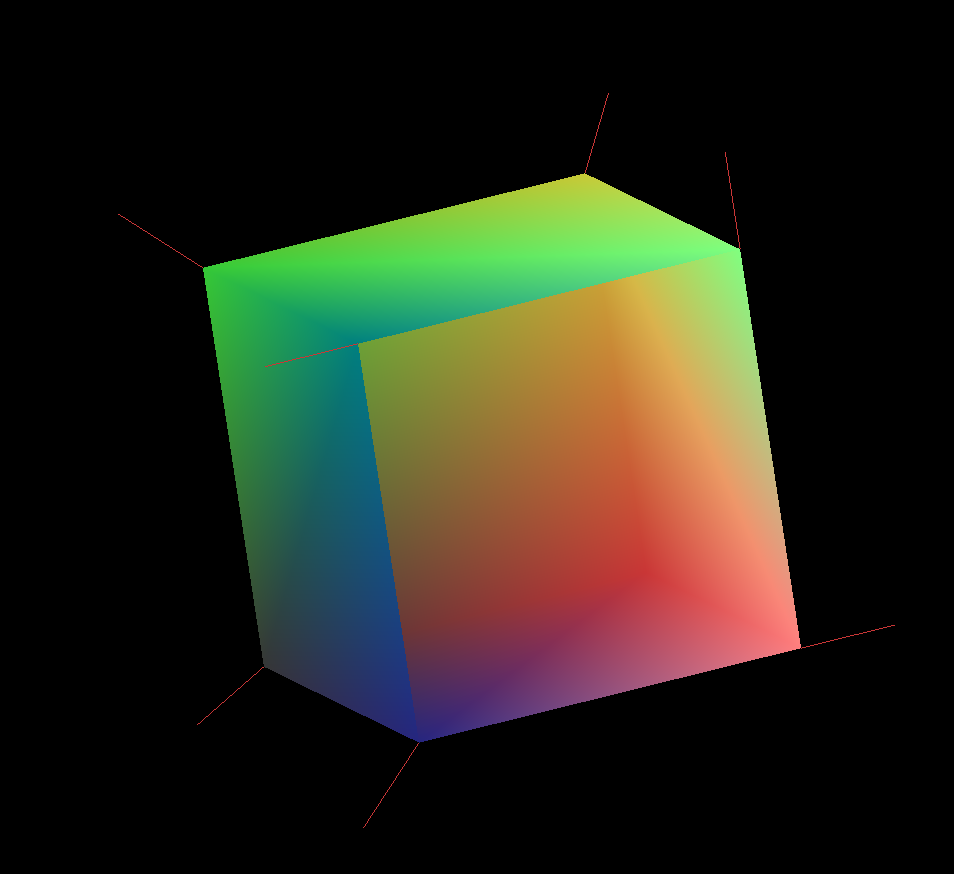
Result for a cube with 1 missing face:

Does this look correct? not entirely Sure how to check correctness

snoken said:
not entirely Sure how to check correctness

Use a detailed mesh, and visualize normals as vectors / arrows. Use them to calculate some simple lighting. Tells a bit more than mapping to colors.

            sum = sum / neighbouringEdges.size(); // division is pointless becasue you narmalize later
            sum.x = abs(sum.x); // huh? why abs? that's wrong!
            sum.y = abs(sum.y); 
            sum.z = abs(sum.z);
            sum = sum.unit();
            vertexNormals.push_back(sum);

There are many ways to calculate vertex normals.
It's possible to weight by angle, area, or both. But usually area should not matter and weighting by angle is preferred.
It's also possible to work just with the cross products between edges from the vertex star, ignoring polygons but skipping boundary edges.

Personally i use an angle weighted sum of those edges, ignoring area and polygons.
When working on quadrangulation, i have tried some alternatives and settled at that, because it has generated the least number of singularities. So angle weights may generate smoother normals than alternatives.
For hard surface modelling artists really want angle weights. Otherwise mesh edits which only change the topology but not the shape can cause different normals, which isn't desired.

But my code is pretty ugly:

vec HEMesh::CalcVertexNormal (const int vertex) const
{
	assert (vertex!=-1);
	int eI = GetVertexEdge(vertex); 
	if (eI==-1) return vec(0);
	vec o = GetVertexPos (vertex);
	vec norm (0);
//int count = 100;
	do {
//if (count--<0) break;
		eI = GetEdgePair(eI);
		assert (eI!=-1);
		int pI = GetEdgePoly(eI);
		
		vec u = GetEdgeVertexPos(eI) - o;

		eI = GetEdgeNext(eI);

		if (pI != -1)
		{
			vec v = GetEdgeVertexPos(GetEdgePair(eI)) - o;
			float U = u.SqL();
			float V = v.SqL();
			float denom = sqrt(U) * sqrt(V);
			if (denom>FP_EPSILON)
			{
				//float dot = vec(u / sqrt(U)).Dot(v / sqrt(V));
				float dot = u.Dot(v) / denom;
				if (fabs(dot) < 1.f-FP_EPSILON2)
				{
					float angle = acos(max(-1.f,min(1.f, dot)));	
					//vec n = CalcPolyNormal (pI);
					vec n = vec(u.Cross(v)).Unit();
					norm += n * angle;
				}
			}
		}

	} while (eI != GetVertexEdge(vertex)); 

	float sql = norm.SqL();
	if (sql > FP_EPSILON2) norm /= sqrt(sql);
	else norm = vec(0);
	return norm;
}
 

@JoeJ Thanks for the code sample. I've taken a crack at trying to implement it and achieved the following:

vec3 Mesh::GetAngleNormal(int id)
{
    long startingEdge = FirstDirectedEdge[id]; // fde for current vertex
    long currentEdge = startingEdge;

    // Each edge points to the ending vertex, to get the starting vertex of the edge, we can use prev(edge)
    vec3 startingVertex = vertices[faceVertices[prev(startingEdge)]];
    vec3 normal = vec3(0.0f, 0.0f, 0.0f);

    do
    {
        if(currentEdge == -1) break;
        // get the position of the pointed to by the current edge 
        vec3 u = vertices[faceVertices[currentEdge]] - startingVertex;

        long nextEdge = next(currentEdge);
        vec3 v = vertices[faceVertices[nextEdge]] - startingVertex;

        // calculate the angle between u and v
        float dot = u.dot(v) / (u.length() * v.length());
        float angle = acos(std::max(-1.0f, std::min(1.0f, dot)));

        // calculate the cross product of u and v and normalize and add it to the normal
        vec3 n = u.cross(v).unit();
        normal = normal + n * angle; 

        currentEdge = otherHalf[next(nextEdge)];

    } while (currentEdge != startingEdge);
    
    normal = normal.unit();
    return normal;
}

for(int i = 0; i < vertices.size(); i++)
{
    auto normal = GetAngleNormal(i);
    normals.push_back(normal);
}

Does this look correct? I feel something is a bit off, though I am not entirely sure if that's just me not being too optimistic in my ability to correctly implement such an algorithm

Normals mapped to RGB

It's clearly wrong. The normals on the open boundary should all form an exact 45 degree angle and lie exactly on the boundary plane.
Those 4 normals should have the expected symmetry, and the triangulation of the quads should not affect those results.
It's actually a good test model to verify angel weighted normals.

In the code i feel doupts regarding the traversal (too many next()?),
and about a missing boundary test (edges still contribute although they are open?).

To debug this, i would print u and v for each step to a file, or eventually visualize them. Goal is to be sure we do not traverse random paths on the mesh. V should become u in the next step.

I would also disable the angle weighting:
normal = normal + n;// * angle;
It should still give somewhat useful results and this way you can remove some math from the search.

snoken said:
I am not entirely sure if that's just me not being too optimistic in my ability to correctly implement such an algorithm

You can only implement what you understand.
If it does not work, you need to debug, to figure out where and why results diverge from your understanding.
You surely have one or more doubts about some things in the code. Then you pick the largest doubt and verify it. Which may be some work, like adding logging or visualization.
If the attempt fails you go on to the next doubt, and continue the search until the bugs are resolved.

In other words: Basic debugging skills. There is no way around it. Nobody else will debug your code, and usually you can't ask anybody for help. So if you lack those debugging skills, you won't come a long way.

This topic is closed to new replies.

Advertisement